
Most stepper motor drivers accept a step and direction input signals. That means we need only two signals for each driver. The step signal is used for making steps and looks like a PWM signal. Each pulse means that the stepper will move for one step (or micro-step). The direction signal is used to signal in which direction (CW or CCW) will the stepper turn.
There are applications where we use stepper motor independently and so appropriate control of the driver is a standard communication protocol such as MODBUS, USB, or I2C.
You can buy stepper motor from https://www.automationtechnologiesinc.com/products-page/stepper-motors.
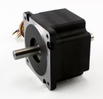
if you researched stepper motors you may have noticed that they have a different number of connecting wires. Most common are motors with two coil windings, 4 wires.
We have found out that the stepper motor driver is a must-have if our design requires the use of a stepper motor since the controller can’t produce enough current and enough high voltage.
There are different types but the chopper drivers offer the best performance. Also, the micro-stepping offers a great solution at first sight but produces a problem of decreased torque. It is still extremely useful but we must use it properly. There are a lot of different ICs available for driving the stepper motor and many already made solutions like PoStep25-32 and PoStep60-256 which provide plug and play solutions and are easy to use.